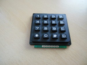
Bei der letzten Lieferung aus China waeren zwei 4×4 Keypads dabei, welche ich fuer eine Projekt benoetige. Abweichend von den Beispielen aus dem Netz, hatte mein Keypad nicht 8 oder 12, sondern 10 Pins. Da die jeweils aussen liegenden Pins keinerlei Funktion hatten, habe ich mich auf die 8 Pins in der Mitte beschraenkt.

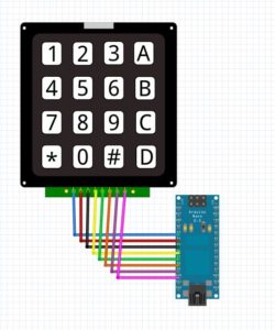
Die Beispiele vom Arduino Playground wollten bei mir nicht so recht funktionieren, also habe ich das Keypad einmal Pin fuer Pin mit dem Durchgangspruefer durchgemessen, und dann eine sinnvolle Kombination gefunden:

Der Code entspricht bis auf die Aenderungen der Belegung fuer die Zeilen und Spalten am Arduino dem Original vom Arduino Playground.
— snip —
/*  Keypadtest.pde
 *
 *  Demonstrate the simplest use of the  keypad library.
 *
 *  The first step is to connect your keypad to the
 *  Arduino  using the pin numbers listed below in
 *  rowPins[] and colPins[]. If you want to use different
 *  pins then  you  can  change  the  numbers below to
 *  match your setup.
 *
 */
#include <Keypad.h>

const byte ROWS = 4; // Four rows
const byte COLS = 4; // Three columns
// Define the Keymap
char keys[ROWS][COLS] = {
  {'1','2','3','A'},
  {'4','5','6','B'},
  {'7','8','9','C'},
  {'*','0','#','D'}
};
// Connect keypad ROW0, ROW1, ROW2 and ROW3 to these Arduino pins.
byte rowPins[ROWS] = { 7, 8, 9, 10 };
// Connect keypad COL0, COL1 and COL2 to these Arduino pins.
byte colPins[COLS] = { 3, 4, 5, 6 };

// Create the Keypad
Keypad kpd = Keypad( makeKeymap(keys), rowPins, colPins, ROWS, COLS );

#define ledpin 13

void setup()
{
  pinMode(ledpin,OUTPUT);
  digitalWrite(ledpin, HIGH);
  Serial.begin(9600);
}

void loop()
{
  char key = kpd.getKey();
  if(key)  // Check for a valid key.
  {
    switch (key)
    {
      case '*':
        digitalWrite(ledpin, LOW);
        break;
      case '#':
        digitalWrite(ledpin, HIGH);
        break;
      default:
        Serial.println(key);
    }
  }
}
— snap —


